Saturday, October 16, 2010

How About Some Flashy Lights? The Method

So I wanted some lights behind the Dixie's head. Flashing, steady, chasing, twinkling, whatever. They had to be battery operated. After some internet searching, I found a site that had plenty of lights. Problem was there were no videos of the lights. So, I took a chance and ordered what seemed to be the best choices.

The site is http://www.littlebrightlights.com/. They have a new site that is easier to navigate (and a more modern design): http://www.lightsforalloccasions.com/. I learned about it from a mention in the receipt for the items I ordered.

The sets I purchased are:
  1. Item Number: 1105-62
    Description: LED Deco String Lights Teeny Bulbs, Green Wire, AA Battery Operated, Multi-Color Twinkling, 0.1 lb
    Weight:      0.1 lb
    Unit Price:  $5.99
  2. Item Number: 6203-28
    Description: Multi-Color LED Deco String Lights, 20 Teeny Bulbs, Green Wire, AA Battery Operated, Flashing or Steady Burn, 0.1 lb
    Weight:      0.1 lb
    Unit Price:  $9.99
Comparison of these sets:

Set #       # Lights  Colors  # Functions  Switch Positions    Description
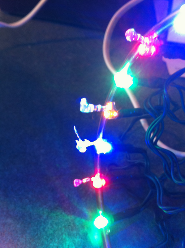
1105-62     10       RGBY         One         Off/On               Chasing (linear sequence).

6203-28     20      RGBY          Two         Off/Flash/On     All  on, All unison flashing

RGBY = Red, Green, Blue, Yellow

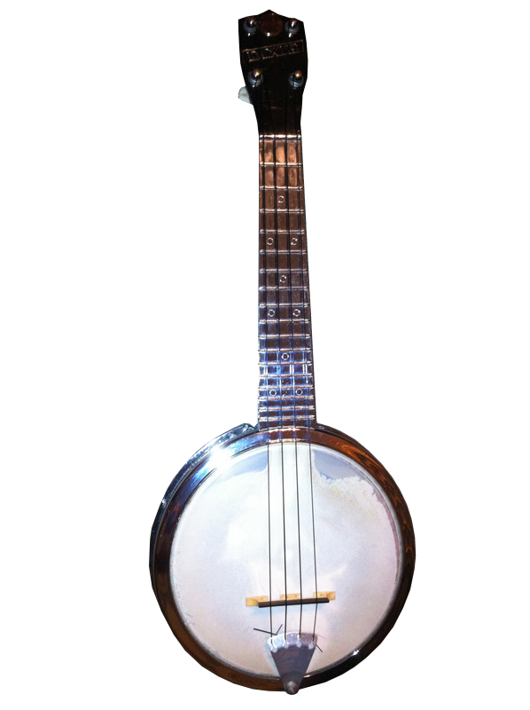
Both sets have a plastic battery holder that takes three AA batteries. The wire(s) to the first light are long enough that the battery holder could be attached to the strap on the instrument. It would be relatively easy to put a polarized plug between the battery holder and the lights, if that would be desirable.

The chasing lights have a small plastic module between the battery holder and the lights.

My first thought was to hot glue the bulbs directly to the inside of the Dixie's body. I tested that idea by temporarily taping the lights in place. After reflecting on that idea, I realized that it would require keeping the lights in place even when they wouldn't be used.

Then the inspiration hit to find some wire that Christmas wreaths are constructed with. A springy type wire that could be bent in an unclosed circle and would fit inside the body of the Dixie.
The "springy wire" would have to fit against the ribs of the body.
If you look closely at the ribs where they meet the body (the inside circle shown above -- where the head rests), there is a lip that might hold a wire so it wouldn't come in contact with the head. Note the photo above is of the body without the head.

So, I went to a Christmas store to look for said springy wire. They did not sell what I was looking for. Then I headed to a local Ace hardware. Walking down the electrical aisle, I saw some copper ground wire. There was #4 and #6 wire. #4 looked like overkill. #6 was smaller and had good spring. I bought enough for two light sets.

The circumference of the "circle of ribs" in the Dixie's body is 16.75 inches. I bought 3 feet of #6 copper ground wire (the wire's sold by the foot). It was about $2.30.

I also bought a small glue gun and glue sticks. A large glue gun looked too bulky. In retrospect, it would have been.

I failed to ask the hardware man to try to measure the wire without straightening it out too much or crimping it. It's easier to make a smooth circle of the wire if it's already in a circle.

My not so smooth circle.
So, I had to "massage" the wire into as smooth a circle as possible. You don't want the ends to meet so it has spring to hold against the ribs of the Dixie's body.

For this light set, I had to mount 20 lights. There are 268/16 inches in 16.75 inches. Dividing 268 by 20 lights, it turned out that the lights would have to be 13.4/16 inch apart. I made marks starting so that the first and last lights would not be right at the opening in the wire.

The copper wire in place. The gap is at the 7 o'clock position.
I actually cut this wire a bit short -- the reason for a gap being there. The wire is springing against the ribs and won't come out under normal conditions (and maybe even hurricane conditions :-) Note that the banjolele head is installed and at tension on this body. If you look closely, you can see pencil marks where someone noted the bridge position on the top side of the head.

To keep the wire in place while I hot glued the lights to the wire, I decided to keep the wire in place inside the body. If you do this, make sure to do as you see in the following photo.

Aluminum foil to protect the head from hot glue.
When I made the second "light ring," I decided not to install the wire in the body. I was able to use a heavy object to hold the wire at the edge of a cabinet.

#1 of 20 lights hot glued!
I tried to keep all the lights glued at the same point on each light so the lights would all be the same distance from the head when everything's together. Because I'm right handed, I mounted the second light to the right of the first. This was my first time to hot glue lights, so I learned as I went along. I discovered that it's best to squeeze a gob of glue and then roll the light up against the glue. The glue gun instructions say to attach the objects to be glued within 15 seconds. With the wire acting as a heat sink, that time's more like 5 seconds, but you still have time to get placement right. Then, hold the light straight for 10-15 more seconds. It takes a bit longer than that for it to cure where it will stay in place tightly.

And, yes, I did have to reglue a couple of lights that didn't hold. I carefully removed as much of the glue from the light as I could without breaking it. I used my fingernails only.

While finishing this project, I've had to reglue at least two more lights. The reason is that the copper wire is too smooth. For this reason, I recommend roughing it up with sandpaper where each light is to be mounted. This way, the glue has something to stick to.

Protect your work area from glue. It will drip from the gun -- thus the extra foil.
Make sure to keep the wiring of the lights away from the tip of the glue gun, too.

All lights glued in place.
See the coils in the wiring between each light? That's not the way the lights came. My first experiment was to wrap the wires around the copper wire in an attempt to fit lights and wires. It didn't work. Too much wire to single layer it and mount all 20 lights. Only 17 would fit that way. Besides, that would create a toroid coil of a sort which might shorten battery life (?). Besides that, the wires would be pushed against the ribs and the insulation would eventually wear thin.

I still have not decided what to do about the wires. They don't really get in the way after I bent them all inward. Having the coils from my earlier experiment actually worked out well to keep the wires from going all over the place.

View when I first removed the light ring.
 When I removed the aluminum foil, I discovered that  a good bit of glue had dripped from the lights to the foil. I had to be careful not to pull the lights along with the foil. See the gobs of extra glue on the lights in the photo above. To remove it, I used wire clippers. But, I didn't clip the glue -- I just clamped onto the glue even with the top of each light. Then I used my fingers to twist the glue until is broke away. The idea was to use minimal pressure near the lights.

Notice that the glue does not affect the brightness of the lights.

Those yellow lights don't quite cut it. Here's the finished ring -- all lights working.

I started to put a cable tie between each light -- nah, overkill!
I did cable tie where the wire leads to the battery holder -- for stress relief.

Update: The wires sometimes snagged on buttons or belt buckles and such, so I took some old hosiery and hot glued it like this:
This keeps the wires from catching on things.
 In the next photo, most importantly, I added glue from each light around the outside of the ring back to the glue at the bottom of the light. It greatly improved each light's solid connection to the copper wire.

Notice the glue strings (lights to the left). They're easily removed.
See the cable tie hot glued at the 6 o'clock position?
This cable tie was left an inch or so long. It's my tool for removing the ring with little effort.

To put the ring into the Dixie's body, grasp the copper wire on each side of the gap, between lights. Place the non-gap side of the ring inside the body against some of the ribs. Compress the gap side until you can get the whole ring inside the body. Now press down on the copper wire to seat it at the bottom of the ribs.

To remove the ring, pull on the cable tie shown above until you can compress the gap to pull the ring free of the body.

Next problem is what to do with the battery case. I was thinking to attach it to the banjolele strap, but it would be better to have it inside the body with the lights. So, what about a piece of right angle aluminum with a hole for one of the neck bolts to hold it in place? Velcro the battery case to it, deep enough into the body so it doesn't get in the way.

Imagine an L bracket coming off the bottom of the top bolt in this photo.
It would be deep enough for the case to fit inside the body.

Another Trip To Ace

Here's what happened, mistakes and all.

I looked for angle brackets that might work with the bolt in the photo above. They either were too long or too short. I opted for flat brackets ("Mending braces") shown below. I figured I could bend one of them at a right angle at the proper point.

While I'm at it, I tried to complete this whole project without having to use any special tools. No tool room either. So, no vice, which would come in so handy.

6-32 bolts, wing nuts, #6 washers, mending brace
In retrospect, I should have gotten bolts that would countersink some in the plastic of the battery case. Four braces came in the package. Also in retrospect, I would have gotten nuts instead of wing nuts.


Not so special tools for bending the brace.
I ended up just using the adjustable wrench and pushed the free end of the bracket hard against the driveway. The bend is not sharp, but it will work.


The 90 degree bent brace.
Now I can see how it fits into the body using one of the neck bolts.


It will fit either this way or turned 180 degrees.
Ah, if I had only thought more carefully about this -- and put the light ring in to check for clearances between the then non-existent bracket and the wiring/lights. Turning the bracket upside down in the above photo looked good until I realized that it would come too close to the wire end of the lights, possibly putting breaking pressure on them. So, I'll have to try the way you see it. Now I have the clearances right!


The location of the bolt hole.
Here, I'm ready to drill the hole in the battery case. This is not the cover to the battery case, it's the part that holds the switch, batteries and wiring.


Correct clearances -- not by a long shot! The battery case is 3/4" deep and will hit the wires/lights below if it's mounted using this hole. Unfortunately, I didn't discover this until I had already drilled the hole :-(


The new bolt hole location.
Fortunately, the holes are in the slot for the middle battery. That's also unfortunate with the size of the bolt head.


Mistake is to the left of the +. But what about battery clearance with the bolt head now?
Yes, the case cover has to be depressed slightly to slide and lock into place at this bolt end of the battery case. Then I remember that batteries can be bent and still work.


I put slow, careful pressure on the battery to flatten this part out some.
The case would now close.


Yippee! Problems solved!


Update: To truly solve the problem, I found some flat head screws and carefully reamed out the screw hole in the plastic case so the screw head would fit flush. No more having to bend the batteries.


Not quite like I envisioned it, but looks like it will work.
Nope!


Remember when I wrote earlier about "in retrospect" and the wing nut?


Side view of the rear of the body, flat across from one side to the other.
The wing nut is outside the body enclosure and will surely snag on something. So, ease of removal is out with the wing nut. I'll put a regular nut and lock washer, and bend the bracket a little further into the body so there are no clearance issues.

I'll add the final results. I did try to play the Dixie with the wing nut as you see it in the photo. It posed no particular problem. It does keep the Dixie from sitting flat on its back, though. 

Here are the two finished light rings. I still have to do something with all the wires, especially those on the chasing light set.
The chasing light set - 10 lights.

Both light rings.
The mass of wires on the chasing lights is required so the lights can turn on/off individually.

Friday, October 15, 2010

How About Some Flashy Lights? Intro

Hokey? Maybe :-) But I wanted to see what LED's would look like behind the Dixie's head.

I'll tell you what I've discovered ASAP. For now, here's some photos:

These either all blink on/off together or stay on steady.

There are 20 lights (RGB & Yellow) -- the yellow ones do not show up as well as the others.

The pattern appearing on the head is the different textures of the head.
Here is this same light set with the lights blinking. The sound is not the lights -- they're silent. Someone else is typing away on a keyboard in the background.
Note that the video can make the flashing lights appear to turn off/on slightly out of perfect sync from one another. They don't. That's a video artifact from the iPhone camera operation. This is my wife's instrument and those are angels on the inside of the head. The lights are not as bright as they appear here. They look much better in "real life."


I do not know why this video got interpreted so that the video is sideways from what I intended, but it gets the idea across. This is 10 sequenced lights that chase one another. Again RGB and Yellow. The problem with this light set is that it cannot be turned steady on. That would be nice. Still, the lights chasing certainly makes for an attention getter (but it could get old quickly, too).

Coloring Clear Nylon Strings

Wouldn't colored nylon strings look good on a Dixie? This is my experience in an attempt to come up with pink  and purple strings for my wife's banjolele.

First I said, "Impossible! Nylon wouldn't dye." I was wrong. I found a company that custom makes colored strings -- http://www.guadalupecustomstrings.com/index.html. The prices were not outrageous. But, that convinced me that it was possible to color nylon strings.

Then I found this site -- you can use Koolaid as the dye! http://www.pburch.net/dyeing/FAQ/drinkmix.shtml

So, here's what happened:

I looked at Koolaid at the store and decided to try several types to see if pink and purple was possible.
Pink and purple strings?
I decided to try these two. I also decided not to do the microwave instructions from the link above. A boiler on the stove top seemed to be more simple to monitor.

A double boiler would insure that the strings don't touch really hot metal?
Problem with doing the double boiler was the smaller pot water never boiled. So I went to that smaller boiler directly on an eye.

The pink lemonade - this photo color is darker that actual.
I let the strings boil for at least 30 minutes. If I do this again, I'll have a lot less water so the color is concentrated. But, make sure that the water doesn't get too low or you might have burnt strings.

The "secret" to dying nylon is to have an acidic mixture. The citric acid in Koolaid is supposed to be enough, but I added some vinegar, too -- just to make sure. I don't think that was necessary.

The "pink lemonade" string.


The "grape" string.
The photos do not reflect the true colors. The pink lemonade strings are a shade lighter than the grape string, but there is not that noticeable a difference. Notice, though, that the string did take on the color -- it just isn't as brilliant a color as I'd hoped.

Side by side, there is a difference, though slight.
I also bought orange and lime Koolaid -- haven't tried that yet.

And, I noticed that if you pay attention to the colors that make up these flavors, I had one (pink lemonade) with red dye in it, and one (grape) with red and blue dye. The difference is the amount of dye. From now on, I'll go with the deepest color dye and adjust the boiling time to make shade differences.

Is there a way to get the colors darker? Maybe a second treatment (or more)?

I'll try that some time in the future. I'll also be buying some strings from Guadalupe. I've seen on at least one ukulele site where they have been discussed. Next time I find that link, I'll make sure to save it for posting here.

Thursday, September 30, 2010

The Newest Dixie Arrived

This post has been edited. Edits are in red.
Dixie #4
This is probably in the best condition of any I've seen.
The back view.

This thing is in great shape. I doubt anyone ever played it. No fret wear even though it has old, rusty metal strings. I don't know how many folks play a Dixie with metal strings. With nylon strings these things are LOUD. I may or may not tighten these metal strings. I'm concerned that the tuning peg buttons may not be able to take the pressure it might take to tune metal strings.

What I was really wanting to see was the tuning pegs -- to compare them with the other three Dixie models.

Notice the dark lines running down the center of the buttons.
The pegs match the buttons of the third Dixie I acquired. That's the one that had a tuning peg button (the plastic part) split when trying to tune the instrument. That split appeared along the dark lines mentioned in the caption of the photo above.

I'm guessing, but I think these tuning pegs are original to the instrument since both sets (from Dixie 3 and 4) are in the same aged condition. Also, the screws match -- they have the built in washers.

The first things to corrode are usually the finish washers.
Luckily, as I've said in earlier posts, the finish washers are available at most local hardware stores. The finish washers are the raised things surrounding each tuning post.

This hardware matches that on the other Dixies.
No hardware was missing from this 4th Dixie. The neck adjustment set screws have not been used here to adjust the neck (covered in another post).

There's no gap between the neck and body (at the red arrow).
You can tell if the adjustment set screws are affecting the neck by looking for a gap. That gap would be between the neck and the body.

I don't think any one of the four Dixie's have an original bridge.

A fourth type bridge, this one a "Grover."
This is the first bridge that has been solid where the bridge presses against the head. After changing the strings and putting all chrome hardware on this Dixie, I set it up to play it the first time. That's when I discovered that strings 1 and 2 buzz on the first fret. That's because this model "Grover" bridge is too low. I may tighten the head, which would probably raise the strings enough not to buzz. Better still, I'll buy another bridge. Tightening an "aged" head can cause it to split. I suspect that when tightening a vellum head it may be best to wet it.

I'm going to take this one apart (maybe with the exception of loosening the head tension). I'll take a photo of the neck where it attaches to the body -- to see which of the other models it matches.

I did take the head off to clean the instrument. I also put all chrome hardware on it.
I think this one's not original and not vellum (calf skin). This is the top view.
Bottom view of the head. You can see the gap in the frame at the 6 o'clock position.

The head's attached to an aluminum frame.


Another view of the frame.


Like another model, the more or less rectangular hole space between the bolt holes is filled in.

I'll add a photo or movie of this "tricked out" instrument soon.

And here they are:

The posts and nuts are chrome.


Another view.

Another view with battery bracket (for lights)

The tail piece bolt is chrome plated too.